[EN/PT] Flow Meter Results
[EN]
After a long two weeks working on an electronic circuit, we finally managed to assemble the complete circuit and make it fully functional. Last week I wrote a post (Flow meter with ultrasonic transducer) and presented some parts of the circuit, such as the pulse train generator using the NE555 IC and the ultrasonic transducers (transmitter and receiver).
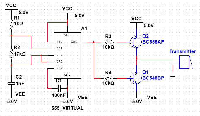
The electronic circuit took a lot more work than expected, because these transducers have certain peculiarities, one of which is that we can't connect their terminals directly to the circuit. In the last post I explained that it was necessary to generate a pulse train with a frequency of 40kHz and a duty cycle of 50%, using the NE555 IC in astable mode. Well, I couldn't connect the transmitter directly to the output of the NE555.
To do this, we had to use a circuit to isolate the transmitter from the NE555, so we used transistors operating as a switch. Another thing we discovered is that these transducers work best with symmetrical voltages (+5 to -5 Volts, for example). So, to generate a pulse train output with symmetrical values on the NE555, you simply need to supply it with symmetrical voltages, as shown in the diagram below.

The pair of transistors is made up of a PNP transistor (BC558) and an NPN transistor (BC548), both general purpose transistors. This configuration gave us a lot of headaches during assembly, because initially we were connecting the base terminal of both transistors directly, which was creating a short circuit, because the base of the PNP transistor was injecting current into the NPN transistor, causing the two transistors to conduct at the same time, creating a short circuit.
The solution, after long hours of discussion, was to separate the bases and put in an individual resistor for both. After solving this problem, the ultrasonic sensor was connected to these transistors. From then on, the transmitter worked perfectly.
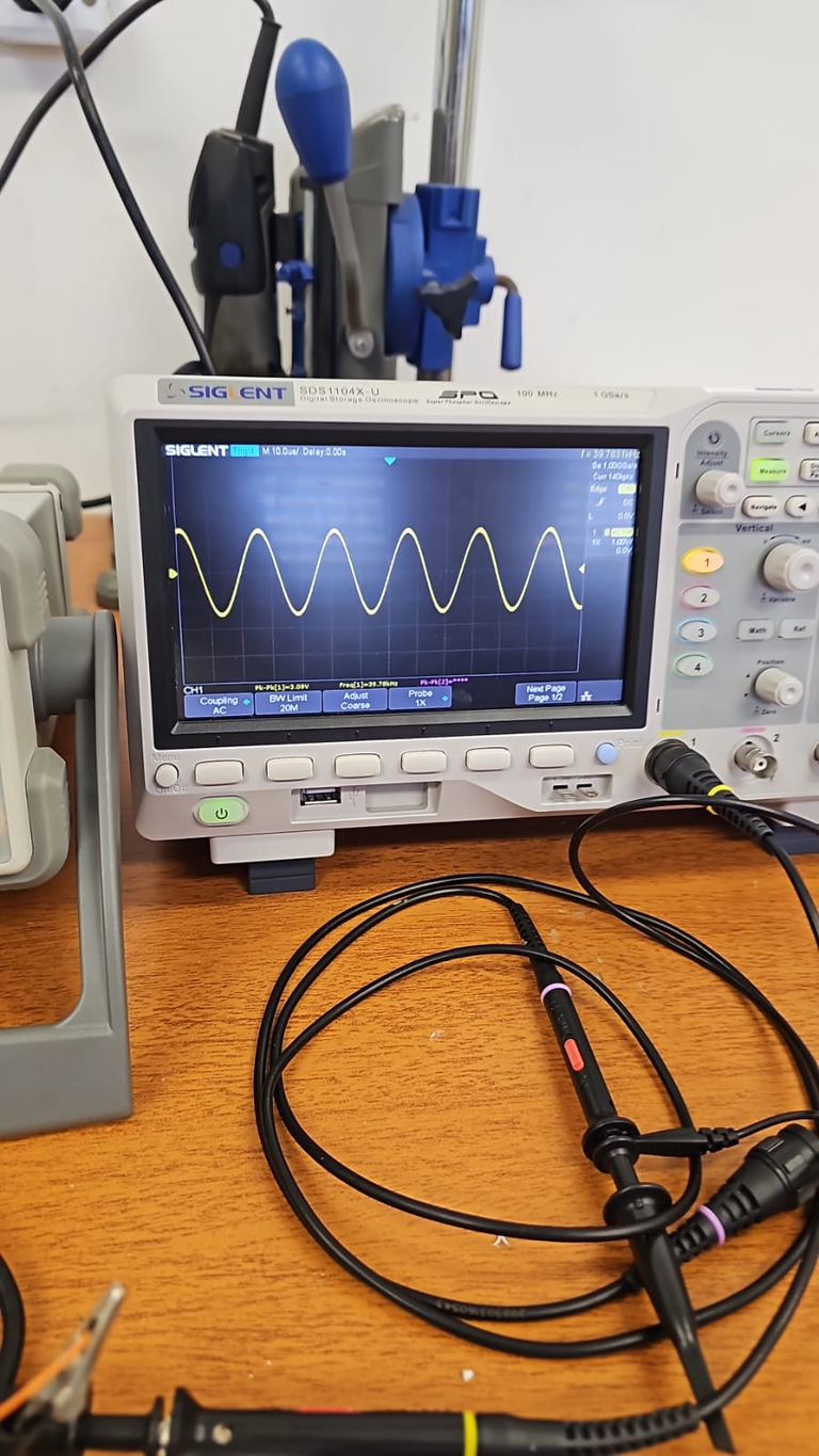
With the transmitter part of the circuit working properly, it's time to show you the receiver circuit and its problems. The transmitter transmits the pulse train signal in the form of a mechanical wave (40kHz ultrasonic sound). When this signal reaches the receiver, it is converted into a sinusoid (not by the receiver, but by the medium, which is air). The image below shows this signal with the aid of an oscilloscope.

The aim of the circuit is to measure the air flow passing through a pipe. It is necessary to make a comparison between the signal transmitted and the one received, so a comparator circuit is needed. In this comparator circuit, the sinusoidal signal is transformed into a train of pulses, so that it can pass through a circuit that will capture the phase difference between the transmitted signal and the received signal, which is basically an XOR (or exclusive) logic gate.

A 3.9K Ohms resistor had to be placed next to the receiver for the ground. Without this resistor, the comparator won't work. The datasheet of the ultrasonic receiver shows a diagram of this resistor.
After the XOR gate we have a 4th order passive filter with a frequency of 100 Hz, which is needed to capture the average voltage, which will be used to calculate the air flow. For a better understanding watch the video, which shows the complete circuit and the results obtained, sorry for the English as we are not native speakers!
I hope you enjoyed this post, sorry if it was too specific!

[PT]
Depois de longas duas semanas trabalhando em um circuito eletrônico, finalmente conseguimos montar o circuito completo e deixar ele todo funcional. Na semana passada eu fiz um post (Flow meter with ultrasonic transducer) e apresentei algumas partes do circuito, como o gerador de trem de pulso usando o CI NE555 e apresentei os transdutores ultrassônicos (transmissor e receptor).
O circuito eletrônico deu muito mais trabalho do que esperado, pois esses transdutores possuem certas particularidades, uma delas é que não podemos ligar seus terminais diretamente no circuito. No post passado eu expliquei que era preciso gerar um trêm de pulso com frequência de 40kHz com duty cycle de 50%, com o CI NE555 no modo astável. Pois bem, não dar ligar o transmissor diretamente na saída do NE555.
Para isso foi preciso utilizar um circuito para isolar o transmissor do NE555, então foi utilizado transistores operando como chave. Outra coisa que descobrimos é que esses transdutores funcionam melhor com tensões simétricas (+ 5 a - 5 Volts, por exemplo). Então, para gerar um saída de trêm de pulsos com valores simétricos no NE555, simplesmente é preciso alimetá-lo com tensões simétricas, conforme mostrado no diagrama abaixo.

O par de transistores é composto por um transistor PNP (BC558) e um transistor NPN (BC548), ambos de uso geral. Essa configuração deu muita dor de cabeça na montagem, pois inicialmente estamos ligando o terminal base de ambos os transistores diretamente, isso esta fechando curto-circuito, pois a base do transistor PNP injetava corrente no transistor NPN fazendo com que os dois transistores conduzissem ao mesmo tempo, fechando curto-circuito.
A solução depois de longas horas de discussão foi separar as bases e colocar um resistor individual, para ambos. E após solucionar esse problema, o sensor ultrassônico foi ligado a esse transistores. A partir desse momento o transmissor funcionou perfeitamente.
Com a parte do circuito do transmissor devidamente funcionando é hora de mostrar o circuito do receptor e suas problemáticas. O transmissor transmite o sinal de trêm de pulsos sobre a forma de onda mecânica (som ultrassônico 40kHz), quando esse sinal chega no receptor ele é convertido em uma senoide (não pelo receptor, mas sim no meio que é o ar). Na imagem abaixo podemos visualizar este sinal, com auxílio de osciloscópio.

Como o objetivo do circuito é medir o fluxo de ar, que passar por um tubo. É preciso fazer um comparação entre o sinal transimitido e o recebido, para isto é preciso fazer um circuito comparador. Neste circuito comparador o sinal senoidal é transformado em um trêm de pulsos, para que possa passar por um circuito que irá capturar a diferença de fase, entre o sinal transmitido e o sinal recebido, que é basicamente um porta lógica XOR (ou exclusivo).

Junto ao receptor foi preciso colocar um resistor de 3.9K Ohms, para o terra. Sem esse resistor o comparador não funciona, no datasheet do receptor ultrassônica existe um diagrama com esse resistor.
Após a porta XOR temos um filtro de 4º ordem passivo com frequência de 100 Hz, necessário para capturar a tensão média, que será utilizado para calcular o fluxo de ar. Para melhor entendimento assista ao video, que mostra o circuito completo e os resultados obtido, desculpa pelo inglês pois não somos nativos!
Espero que tenha gostado deste post, desculpa se ele foi muito específico!

Posted Using InLeo Alpha


Rapaz o conteudo que você ta gerando é muito legal!!! Legal que ta bem explicadinho para que qualquer um possa replicar! Meu sonho é ver mais posts como esse de várias areas cientificas nos mostrando que Hive pode ser um local de compartilhar esse tipo de material.
Muito Obrigado! Seria realmente muito legal que isso acontecesse, diferente da WEB2 que está cheia de conteúdo que não agrega nada, dancinhas e brigas políticas.
Mesmo assim a Hive já é um ótimo lugar, por não predominar esse tipo de conteúdo inútil!
Bzzz! Parabéns, @elderdark! Demorou um pouco, mas o circuito está funcionando! Eu também sabia que os transdutores ultrassônicos podem ser chatos, mas o resultado valeu a pena. Que trabalho, né? Lagg-bzzz! #hivebr
Vlw @PixBee! Sempre dando um apoio moral por aqui! Continue sempre ativo!
Ahah, obrigada, amigo! Eu sei que os ultrassônicos podem ser um pouco cansativos, mas bzzz, o resultado é incrível! E você, como está a luta contra o malware?
Obrigado por promover a comunidade Hive-BR em suas postagens.
Vamos seguir fortalecendo a Hive
Your post was manually curated by @Shiftrox.
Delegate your HP to the hive-br.voter account and earn Hive daily!
🔹 Follow our Curation Trail and don't miss voting! 🔹
!hiqvote
Your new share balance will be effective in the upcoming prize pool draws from now on, forever and ever...
DrawMatic shares last a lifetime!
The more shares you own, the higher your chance of winning in each and every upcoming draw! 😎
Rapaz, para mim é grego esses gráficos kkk, mas fico impressionado com tudo isso, bem da hora de compartilhar isso com a galera! Valeu um abraço!
Vlw! Grande Shiftrox, obrigado por passar aqui!
Por nada meu amigo! Forte abraço!
Thanks for your contribution to the STEMsocial community. Feel free to join us on discord to get to know the rest of us!
Please consider delegating to the @stemsocial account (85% of the curation rewards are returned).
You may also include @stemsocial as a beneficiary of the rewards of this post to get a stronger support.
@gwajnberg, the HiQ Smart Bot has recognized your request (1/2) and will start the voting trail.
In addition, @elderdark gets !PIZZA from @hiq.redaktion.
For further questions, check out https://hiq-hive.com or join our Discord. And don't forget to vote HiQs fucking Witness! 😻